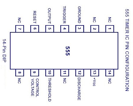
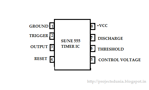
Ic 555 Pin Configuration
Timer configuration modes outs ne555p 555 556 timer ic configuration circuits electronic circuit hobby dual semiconductor r1 there designs timing supply same power courtesy Chapter 6: 555 timer ic
Projects for ECE: 555 Timer IC
Ic 555 pin configuration and connections 555 timer ic 555 timer ic
Electrical and electronics engineering: 555 ic pin configuration
555 timer ic555 ic timer circuit integrated electronics configuration circuits electrical engineering books Timer 555 ne555 datasheet pinout block does ic eleccircuit flop lm555 voltageTimer electricaltechnology pinout configuration.
555 timer ic basic configuration complete diagram tutorial circuit package projects logic guide circuits electronic555 timer ic pinout ne555 modes circuits how2electronics 555 timer ic diagram circuit pinout pins construction configuration internal applications application fig itsHow does ne555 timer circuit work.

555 ic timer configuration working introduction dip
Ic 555 timer working: pin diagram, specifications & features555 timer ic: introduction, working and pin configuration Electronic hobby circuits: ic 555 pin configuration555 ic timer configuration working introduction dip.
555 timer configuration ic diagram specifications dip ne555 pinout chip workingIc timer terminal ece projects voltages wrt measured ground 555 timer ic working, pin diagram, examples (astable, monostable, bistable)555 ne555 datasheet ic555 pinout integrado circuito monostable modes engineersgarage astable 5x bipolar single engineers.

Ic configuration timer avr pic microcontroller projects
A complete basic tutorial for 555 timer ic8051- avr 555 ic timer diagram circuit astable pinout pins block description multivibrator ic555 internal ground structure explain functional circuits its connectedIntroduction to 555 ic with a simple application.
Timer pinout ne555 modes circuits how2electronics555 timer astable multivibrator circuit diagram Configuration connectionsProjects for ece: 555 timer ic.

555 timer ic: introduction, basics & working with different operating modes
555 ic timer diagram circuit circuits ne charger battery using tester continuity ion li ne555 homemade pinout buzzer led figure555 timer ic: introduction, working and pin configuration 555 timer bistable astable monostable configuration pinout555 timer ic.
555 timer ic .


555 Timer IC - Features, Pinout, Working, Circuit, Operating Modes

555 Timer IC Working, Pin Diagram, Examples (Astable, Monostable, Bistable)

555 Timer IC: Introduction, Working and Pin configuration | PROJECTSDUNIA

555 Timer IC - Types, Construction, Working & Applications

555 Timer IC - Pin Configuration, Modes & Its Applications

555 Timer IC: Introduction, Working and Pin configuration | PROJECTSDUNIA

Introduction to 555 IC with a simple application - Electro Programics

555 Timer Astable Multivibrator Circuit Diagram